Previously we wrote about the use of the pin connector in Solidworks simulation. It’s a great aid in fast modeling of machines with connected parts, but we highlighted a shortcoming. The pin connector in Solidworks has always mapped surfaces onto sets of rigid cylinders for simulation. This allows the intended connection and articulation, but hurts accuracy of stress results immediately around the pin.
We also noted that there was a problem in Solidworks 2018; the pin formulation was improved to allow connection of more than two cylinders, but in many cases the connector no longer permitted free rotation where expected, like over a sheave. For Solidworks 2020 improvements to the connector were promised. A fix was delivered, and a whole lot more.
The previous post is at:
https://www.stonelakeanalytics.com/2019/07/07/connector-or-crutch/
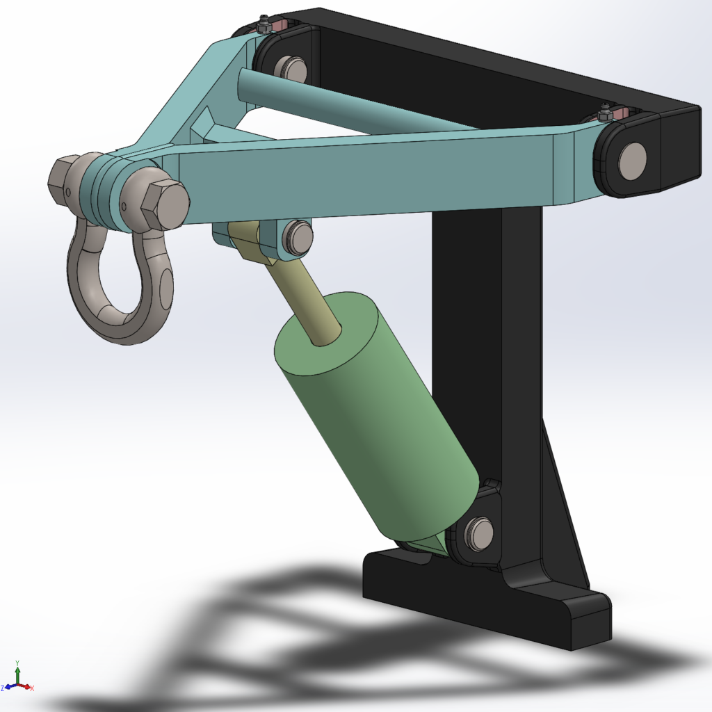
In the example model, this bushed joint was modeled in full no-penetration contact, and with the joint considered as one pin connector. When using a pin connector, the stress result did not show a serious concentration at the thin wall of the grease fitting hole.
We found that using full no penetration contact showed a much higher (and realistic, based on real experience with very similar geometry on a broken machine) stress, at a cost of a sixty-fold increase in run time [25 minutes vs 24 seconds].
The first thing we did with Solidworks 2020 was to verify that the pin connector now allows rotation when desired. But now we’ve explored the rest of the new functionality of the joint; the pin connector doesn’t have to be a rigid body any more. In the connector setup there is a new option – the “Distributed” connector type.
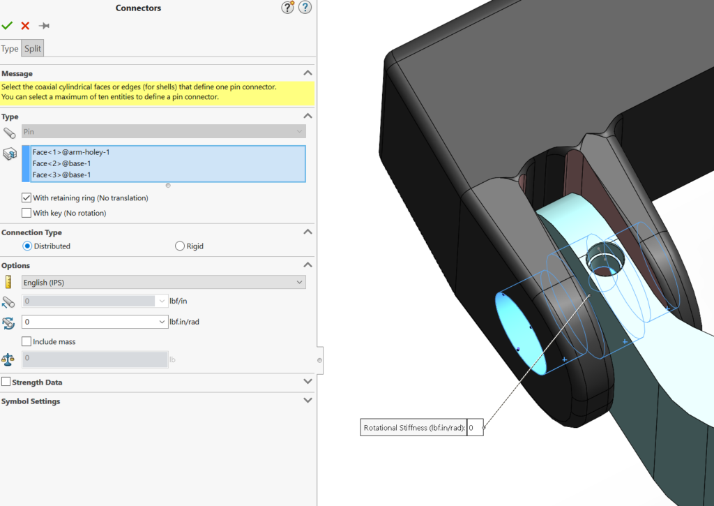
We can still pick multiple cylinders, but there’s a new formulation available for how those cylinders become related. A little more detail is available in the Solidworks help files. The real question is how does it affect our results?

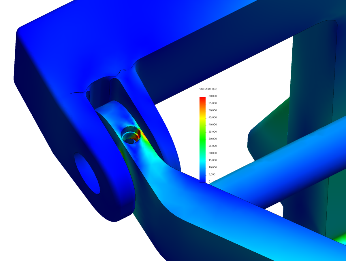
Now we can see the distinct stress concentration expected in the thin wall. The surface of the pin bore in the arm is now free to stretch realistically away from the pin diameter.
The next question is how does it affect run times? Remember that running full contact on this model took dozens of times longer. Converting all the pins here to “distributed” increased run time by just 30% [25 seconds versus 19 seconds (fresh runs on a different computer)].
The new pin formulation is used for bolt connectors also. In an example for our forthcoming book we have a welded bracket bolted to a base with four through-bolts with nuts. In one study we modeled the bolts and nuts as solids.
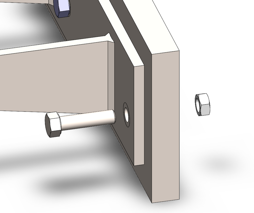
The nut is fixed on the bolt with a pin connector, either with the old rigid pin or the new distributed connector. The pair is in no penetration contact with the bracket and base. This arrangement is the only way to get the most accurate picture of stresses near and through the bolt.

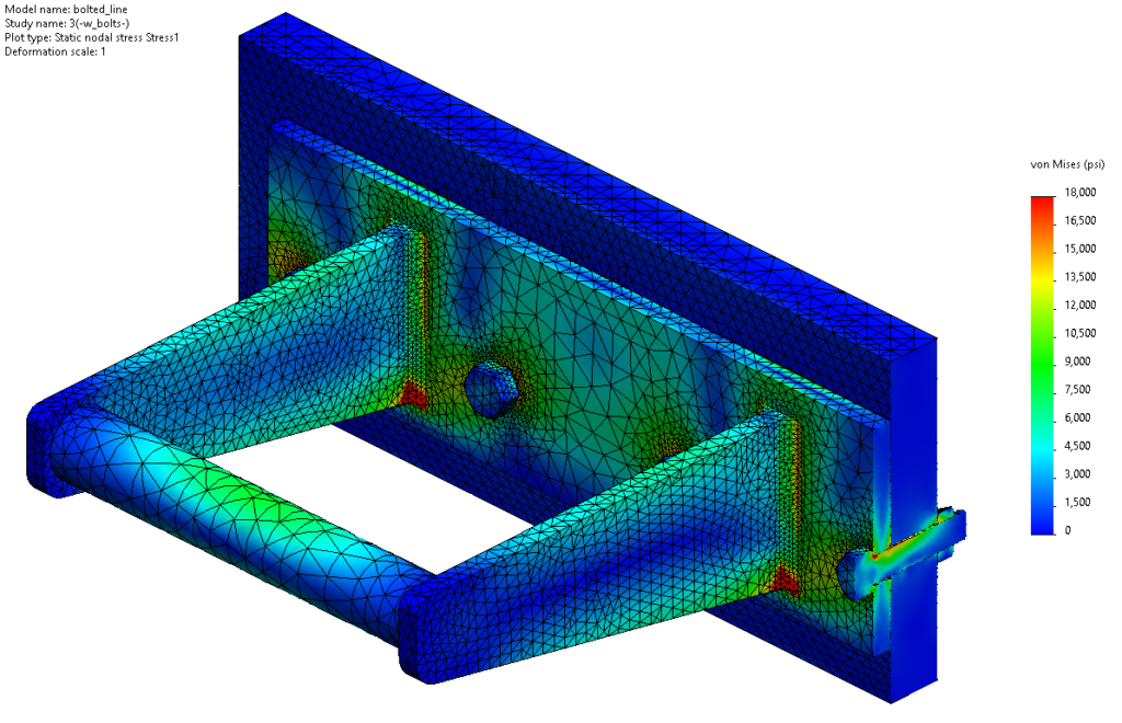
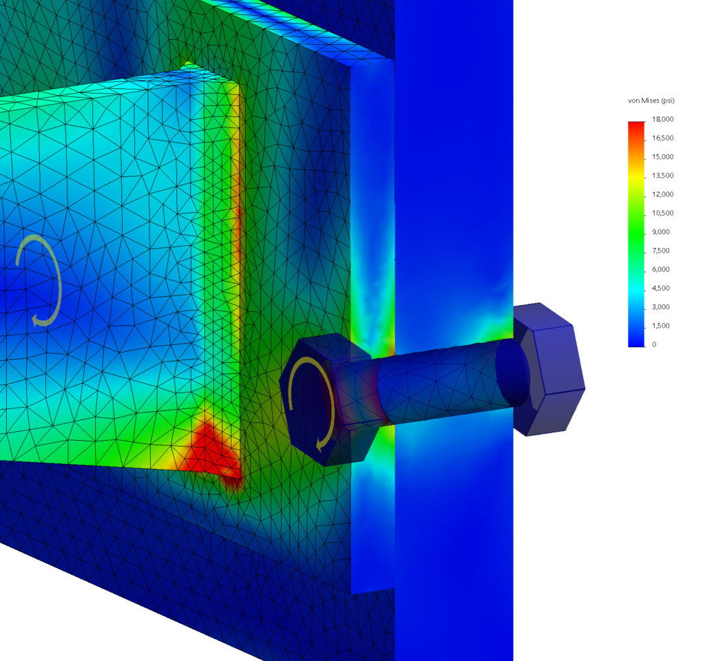
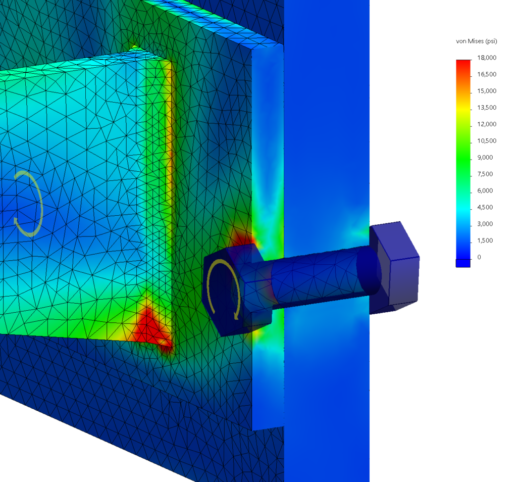
With the legacy pin connector there is no stress shown through most of the solid bolt. With the new formulation a classic stress field is seen through the shank.
Now instead of literal solids we try it with the bolt connector. This won’t show any internal stresses in the bolt, but does allow us to input bolt pre-load and correctly account for bolt stretch during loading. Results are shown with the classic bolt connector and with the new distributed style.
With the old style bolt stresses around the bolt holes are about constant. Using the new distributed bolt more of the expected variation can be seen. We’re going to keep working with this; look for more information in Solidworks Simulation for Real Machines, due out in early 2020.
We have what looks a great new tool for accurate simulation of bolted assemblies and machines. The user is encouraged to experiment within their applications to see what the new bit of kit can do for good and fast results. Stone Lake will continue to work toward quick turnaround of reports that show clients what’s really going on in their products.