In the previous piece we looked at beam bending with solid and hollow sections, with different numbers of elements across the body or the wall thickness. Here we switch from bending to torsion. In torsion open shapes behave very different from closed sections.
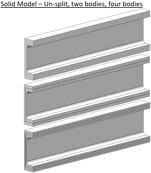
By closed section we mean something like the cylinder below. The section is made “open” by cutting a lengthwise slot through the entire length [the classic example for this is to take a whole toilet paper tube then cutting it once and seeing the difference in twisting stiffness].
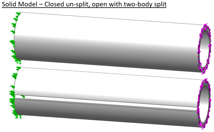
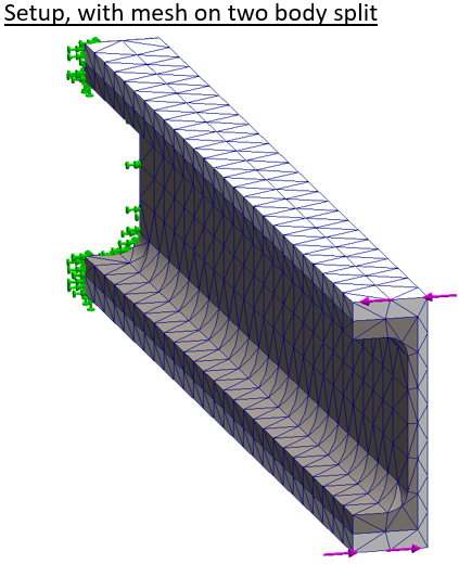
The cylinder is fixed on the left end. A pure torque is applied to the right end face. The second shape shows the slot cut and a split which cuts the shape into two bodies.
Again we mesh the body first with linear elements, then second order elements. The body is split to force multiple elements through the thickness at the same mesh settings. Since a closed cylinder is very efficient in torsion displacements are very small and we won’t plot displacement here.
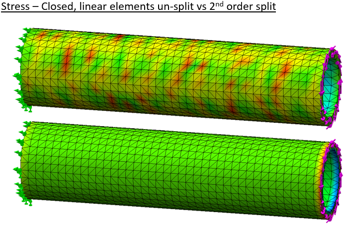
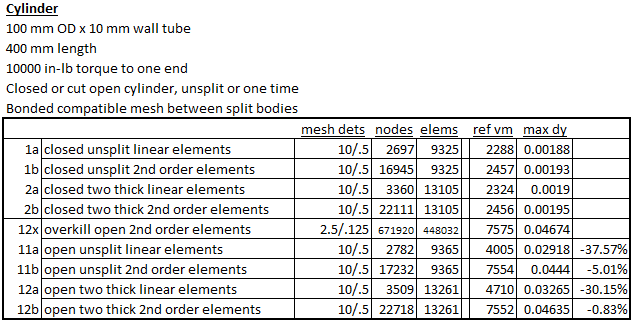
Results on the cut cylinder follow. Even with coarse linear elements the result looks realistic.
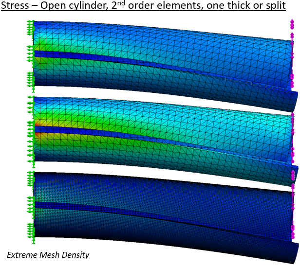
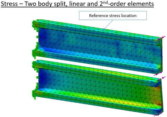
But when we use high quality mesh the body is much more flexible. Stress predictions also change significantly. The extremely fine mesh result is our reference.
Tabulation of results shows again that the use of second-order elements goes a long way toward delivering ideal results.
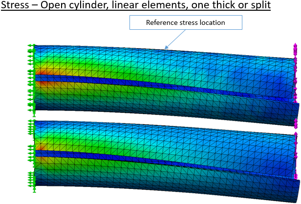
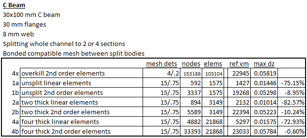
The engineer knows that asymmetric open sections are very poor in torsion, but sometimes that loading has to be borne. A simple C-channel is modeled and split into two or four bodies.
The setup has the left end fully constrained again. The right end has a moment applied by opposing forces along the top and bottom edges.
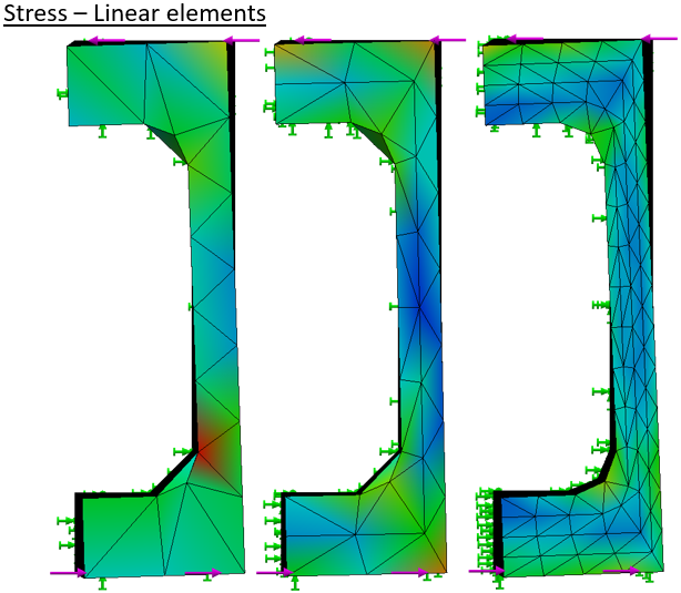
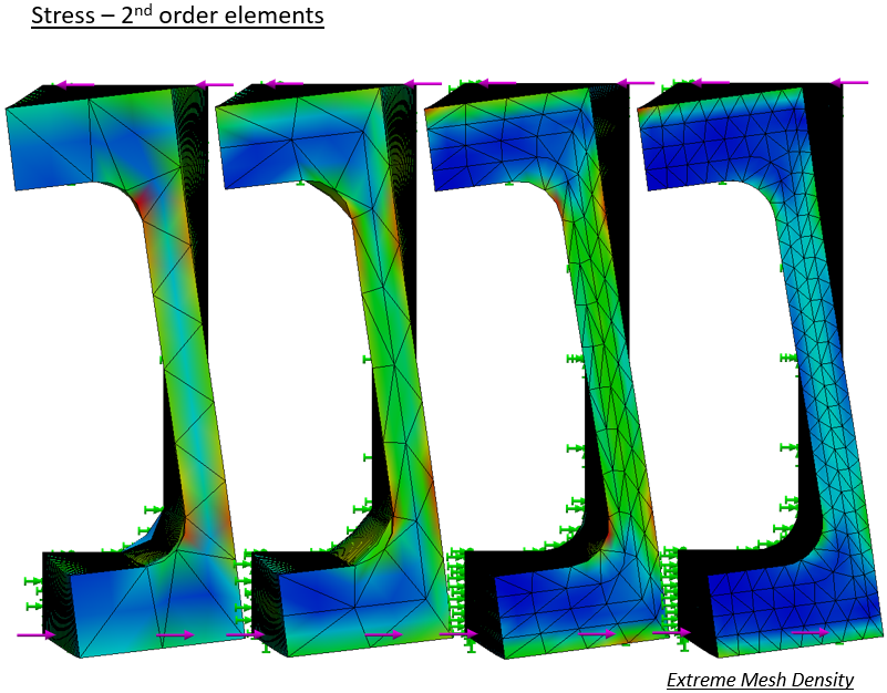
Stress results follow a now familiar pattern. With a coarse linear mesh the stress pattern is ‘lumpy’ and the deflection is very low.
Viewed end-on the relative deflection is readily compared.
Twist of the high quality meshes is much greater at any density.
The tabulation shows the advantage of the “high-quality” mesh. In this case the mesh density needs more than two elements across the thickness to bring good results.
In conclusion we find that relatively coarse solid meshes with second-order elements usually provide good results in Solidworks Simulation. Relative importance of mesh density varies with local loading conditions. It is advisable to run mesh sensitivity studies, at least on any new class of problem. Our usual practice is to get what we think is a good result, then near then end of the project bump up the mesh density on one study to the maximum practical mesh size. After a long (maybe overnight) run, the results are compared to check that there is not a large divergence.
Do you have solution files for Solidworks Simulation for Real Machines book?
Down at the bottom of
https://www.stonelakeanalytics.com/2021/01/30/solidworks-simulation-for-real-machines/
is a “download now” button.