Solidworks Simulation for Real Machines

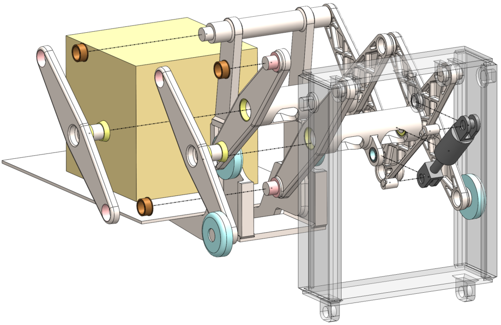
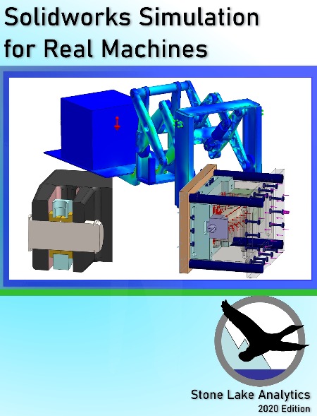
Recently published by Stone Lake Analytics is this example-filled guide to modeling of multi-component machines.

The principles and techniques detailed are not restricted to Solidworks. Users of most contemporary FEA tools can gain insight from this work. Engineering managers will learn what can be accomplished in fundamental linear-static tools.

The book is an illustration of Stone Lake Analytics’ capabilities and expertise.

Case studies progress through a series of mechanical assemblies. Machine elements from simple pins to chains-over-sheaves to pairs of fluid cylinders are represented in different ways.

Human and computer costs are compared for different solutions against trade-offs in accuracy and presentation.

Color paperback and e-book available from Amazon and select retailers.

Models used in the book can be downloaded here,

Mesh Density Challenge 2 of 2

In the previous piece we looked at beam bending with solid and hollow sections, with different numbers of elements across the body or the wall thickness. Here we switch from bending to torsion. In torsion open shapes behave very different from closed sections.

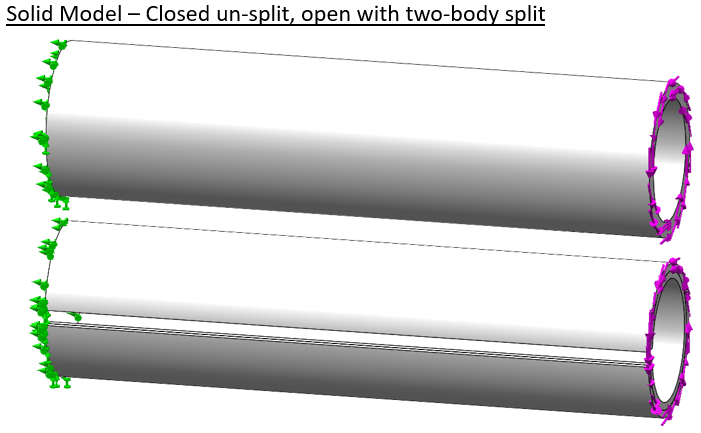
By closed section we mean something like the cylinder below. The section is made “open” by cutting a lengthwise slot through the entire length [the classic example for this is to take a whole toilet paper tube then cutting it once and seeing the difference in twisting stiffness].

The cylinder is fixed on the left end. A pure torque is applied to the right end face. The second shape shows the slot cut and a split which cuts the shape into two bodies.

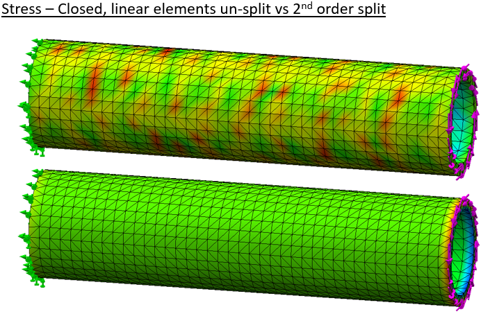
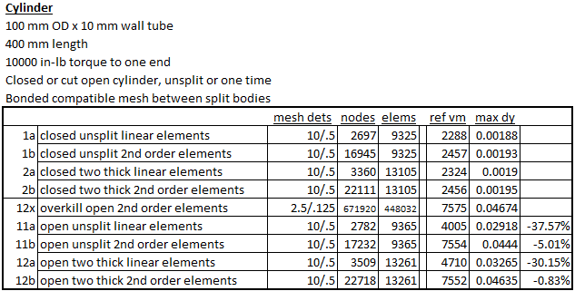
Again we mesh the body first with linear elements, then second order elements. The body is split to force multiple elements through the thickness at the same mesh settings. Since a closed cylinder is very efficient in torsion displacements are very small and we won’t plot displacement here.

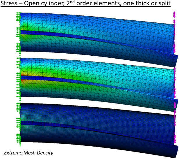
Results on the cut cylinder follow. Even with coarse linear elements the result looks realistic.

But when we use high quality mesh the body is much more flexible. Stress predictions also change significantly. The extremely fine mesh result is our reference.

Tabulation of results shows again that the use of second-order elements goes a long way toward delivering ideal results.

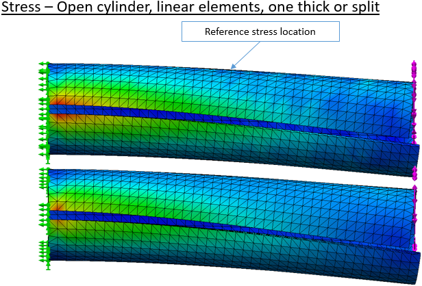
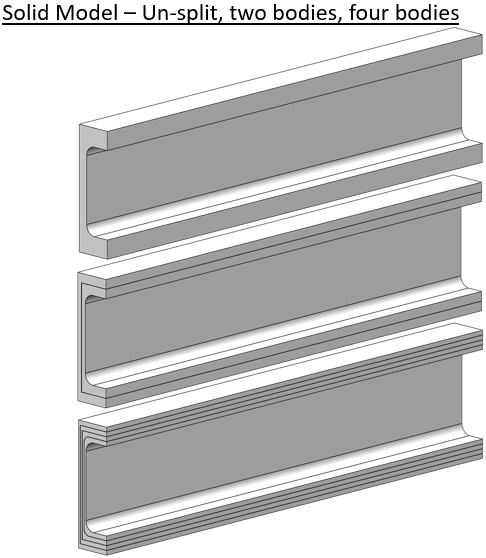
The engineer knows that asymmetric open sections are very poor in torsion, but sometimes that loading has to be borne. A simple C-channel is modeled and split into two or four bodies.

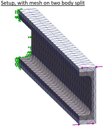
The setup has the left end fully constrained again. The right end has a moment applied by opposing forces along the top and bottom edges.

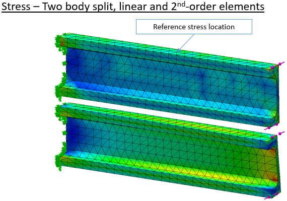
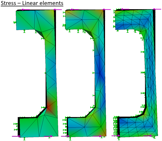
Stress results follow a now familiar pattern. With a coarse linear mesh the stress pattern is ‘lumpy’ and the deflection is very low.

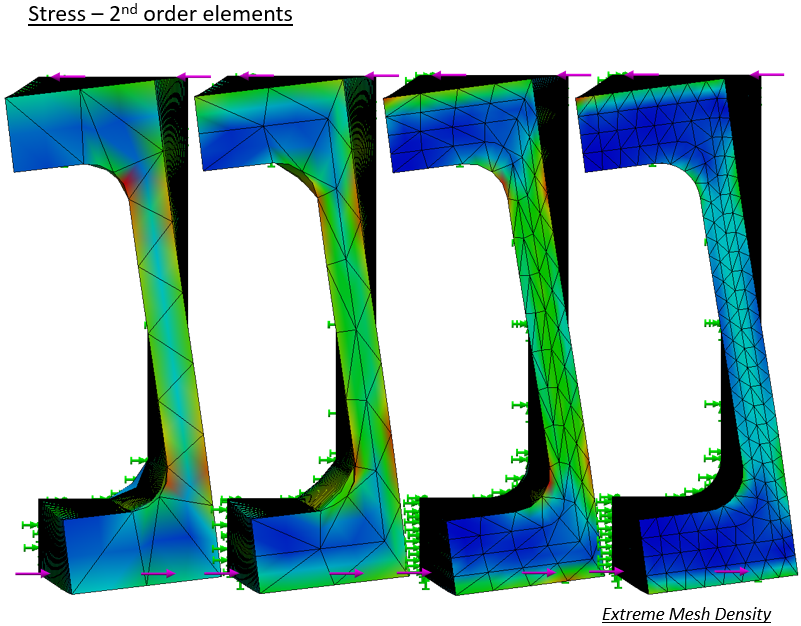
Viewed end-on the relative deflection is readily compared.

Twist of the high quality meshes is much greater at any density.

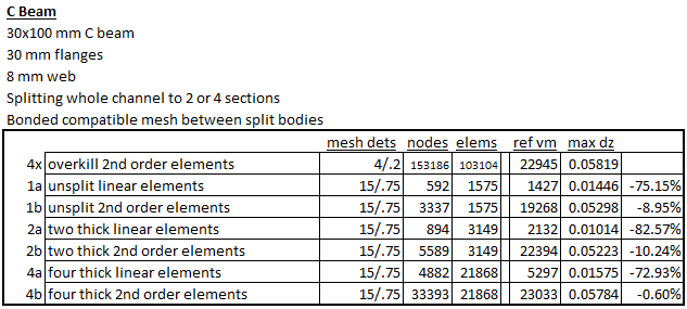
The tabulation shows the advantage of the “high-quality” mesh. In this case the mesh density needs more than two elements across the thickness to bring good results.

In conclusion we find that relatively coarse solid meshes with second-order elements usually provide good results in Solidworks Simulation. Relative importance of mesh density varies with local loading conditions. It is advisable to run mesh sensitivity studies, at least on any new class of problem. Our usual practice is to get what we think is a good result, then near then end of the project bump up the mesh density on one study to the maximum practical mesh size. After a long (maybe overnight) run, the results are compared to check that there is not a large divergence.

Sample Report – Reach Boom

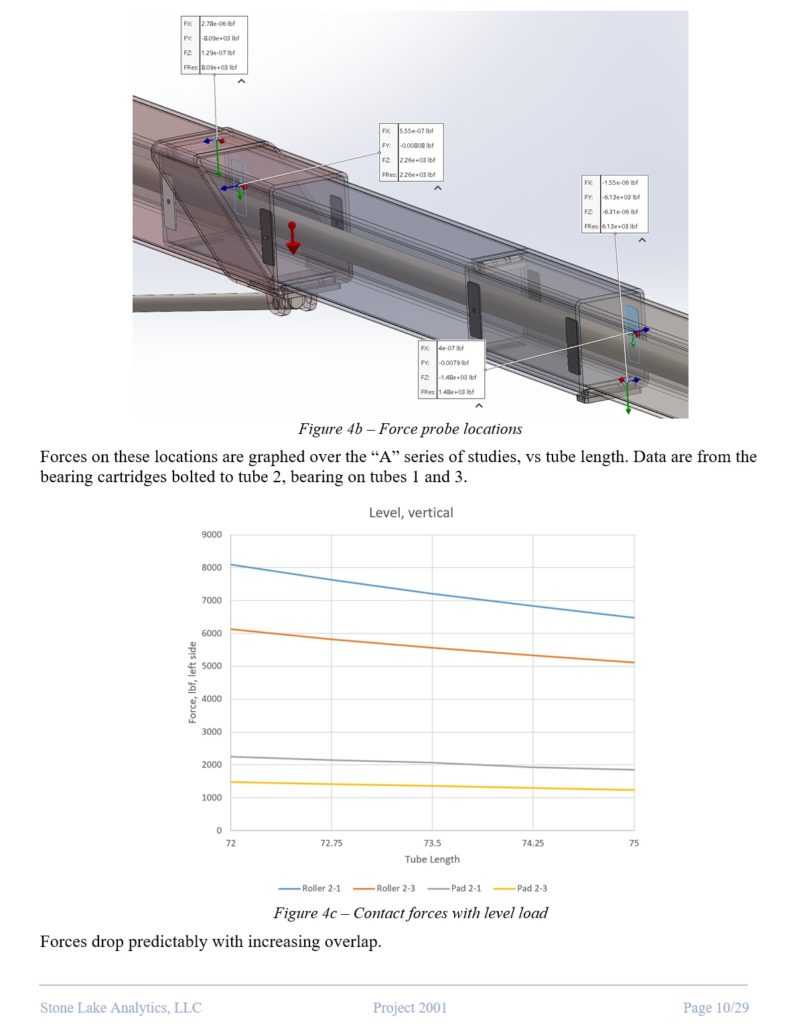
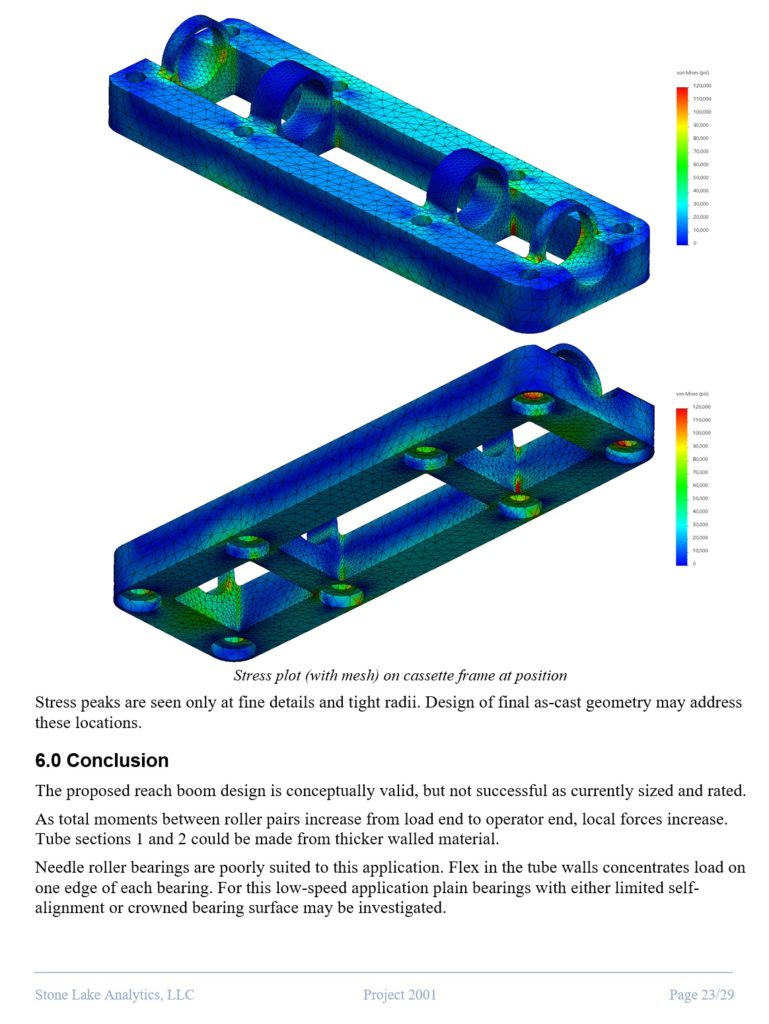
Most of our work is proprietary to Stone Lake clients. It’s rare that we get a chance to share examples of what we’re doing. So we put some time into designing a realistic machine, one which requires some of the best techniques in our tool box, to write a report for public access.

In this study a telescoping crane boom is loaded at extension in several orientations and configurations. The overlap between sections is varied and resultant hardware forces tabulated for each loading.

The published report is meant to be an example for potential clients to know what Stone Lake expects to create as a final deliverable. Go to the sample report page to get a complete copy.

Friction Clamping in Simulation

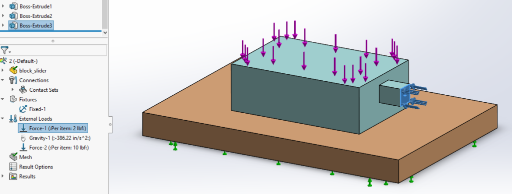
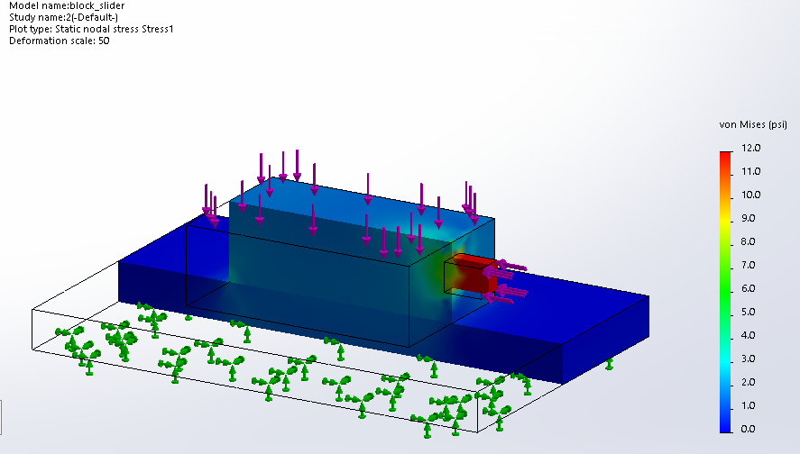
A question was recently posed in the Solidworks user forums about trouble solving a tough problem. A two-piece clamp-on bracket is bolted to itself on a length of pipe. Some live load is mounted to the bracket. The problem is trying to simulate the load on the bracket, which stays on the pipe only by friction.

I do a lot of contact analysis. I have found friction to be a tough thing for static solvers, but it does work. However, where I’ve wanted to use friction, I often realize that the objects staying together is an assumption of the problem in the first place. I’ll usually bond one contact pair, let the others slide, and go back to check resulting forces after getting a good solve.

This post got me thinking and I went ahead and made a couple models to tinker with.
The first question is – Can Solidworks Simulation solve a model with friction as the only restraint on loaded bodies?

Yes is the answer.

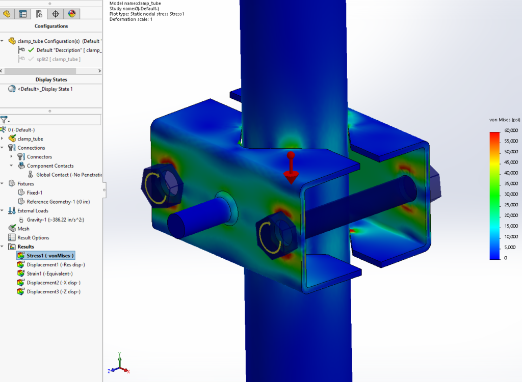
Here a bolted pipe clamp is loaded only by gravity. For stability one vertex is constrained in one plane. With a coarse mesh and global no-penetration contact it solves in a few minutes. (It’s better to split surfaces and assign contact manually in discrete pairs; that gives both more control and more information about what’s going on.)

But lets look at it another way – assume that the static friction is sufficient. If it’s not, the design has failed and the static solver cannot give an answer anyway. Remember that coefficient of friction is an input. You make it up, based on something external to the simulation.

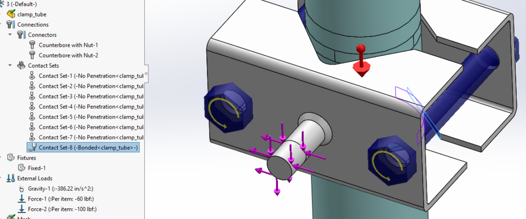
So we bond one or more of the mating pairs.

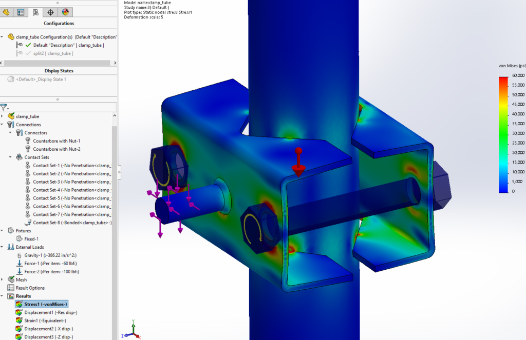
It takes almost an hour to solve, with loads applied in addition to gravity.

The bolt preload may be too much for these shapes (half inch bolts ‘looked’ right, but here is where a series of quick simulations can readily improve a design!). But the stress pattern and deflection are totally reasonable.

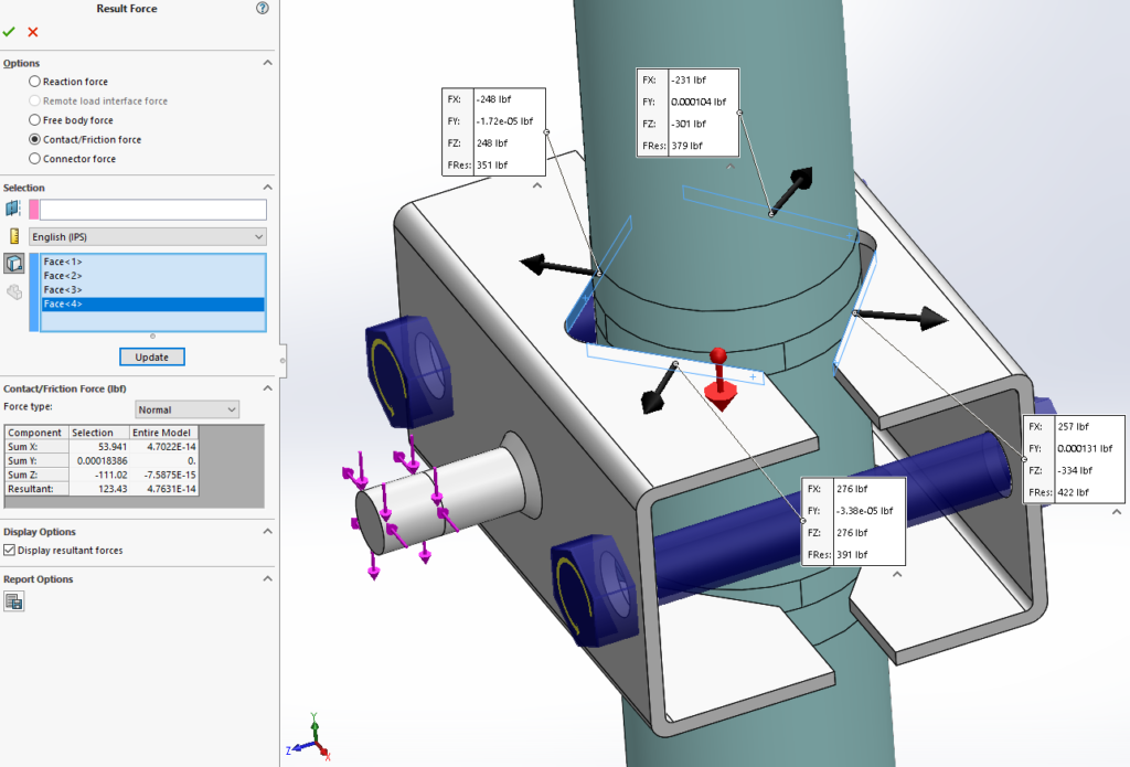
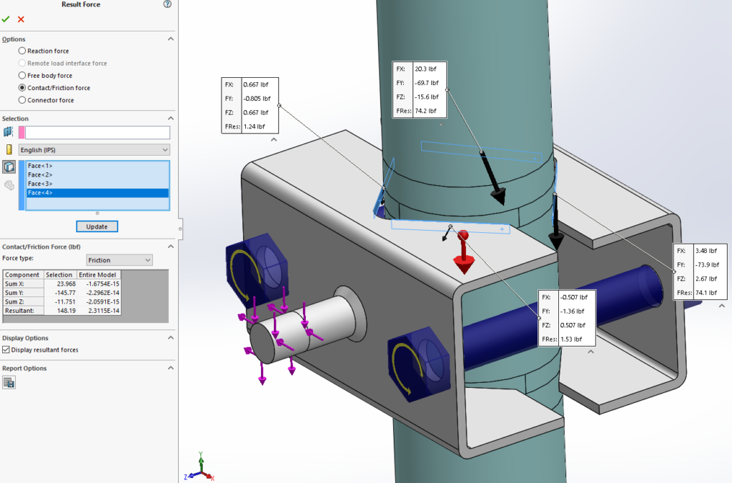
Having manually assigned contact pairs, we can check the normal and supposed friction force at each.

There might not be enough friction on the back side (at 0.2 CF). Pre-load is reduced on the front, but friction is not called for there. A similar check on the bottom four contacts shows they probably hold. But all of this depends on how good we think the friction is.

There are other way to look at this. One could put a prescribed displacement at the load, based on a best guess. What displacement? Try a fully bonded solve with live forces then use that resultant displacement.

We don’t yet have a fully ‘loose’ solution, with nothing but pure no-penetration contact. But with an honest approach we can get a much easier solution that does validate the design, if it is actually valid.

Solidworks Simulation Benchmarks (for real studies!)

Shawn Mahaney – Lead Analyst

INTRODUCTION

I was looking in the last few month at new computer hardware. Ok, in actuality I am always looking at new computer hardware. It’s where I make my living, and watching it evolve and perform can be pretty cool.

The main workstation PC in my personal office is, and has been for too many years, a collection of old and new parts stuffed into an ATX case that’s seen multiple upgrades of every sort. In 2012 it got a motherboard mounting the living legend Intel i7-3770k processor (quad core, 3.5 GHz). The system got set up with 16 GB of RAM, which was generous at the time. But Stone Lake has been tackling some larger jobs, and asking more specific questions of the simulation tools. We’re seeing bigger meshes and using more contact and articulation – more memory is needed.

That old 3770 is still quick enough to crank through tough jobs in a reasonable time, but it’s chained to DDR3 memory, at 667 MHz. Recent experience has led me to believe that RAM speed is the bottle-neck for some of our work, which often needs 64 GB systems. So I was determined to get a quad-channel RAM system, and decided I would benchmark a few systems to see for myself just what matters for the kinds of problems we solve.

There are many computer benchmarks to pick from. Few that I’ve seen deal with large data sets, even Solidworks simulation benchmarks. So I picked a couple problems which take up a decent bit of memory, enough to need a 16 GB system. Solidworks simulation run times for them are compared here to raw benchmark results.

THE STUDIES

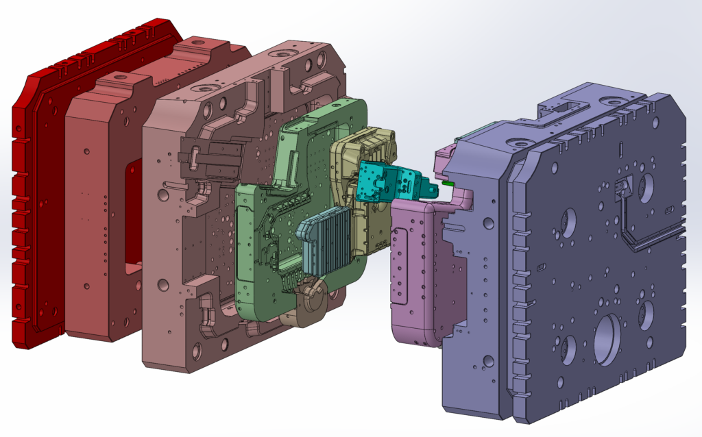
The first study is of a die cast machine die holder. This multi-ton block of steel holds together all the die pieces for a high pressure metal casting process, under about 6 million pounds of clamping force. It has dozens of cooling lines and clearance passages for myriad other fluid and mechanical functions. It is simplified somewhat from the final CAD file, but we usually lean toward leaving in detail. When the model looks more like the real thing, there are fewer doubts for the client.
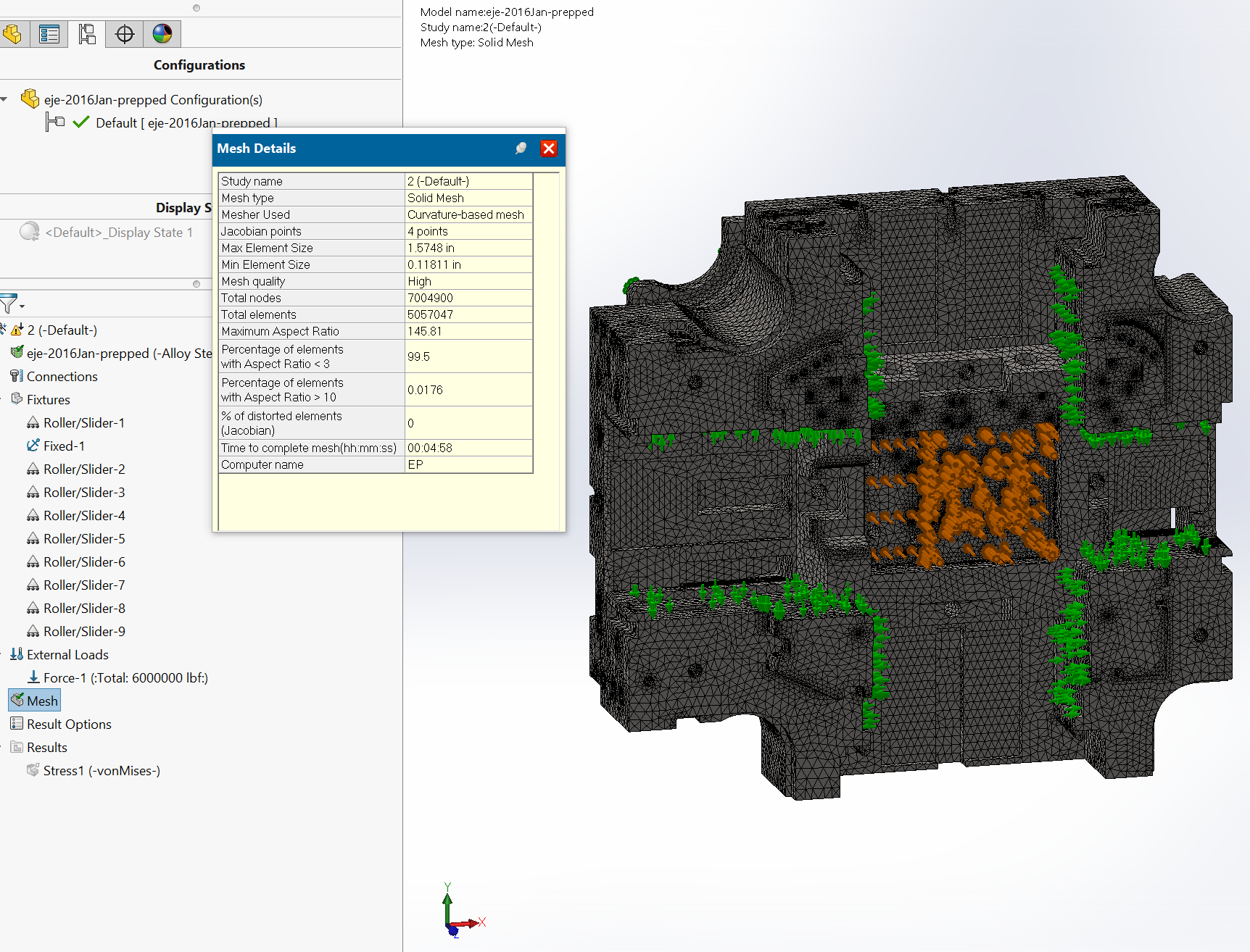
The mesh comes out over five million elements. Mesh creation peaks using over 7 GB of RAM. An iterative solver must be used to fit the problem in a 16 GB machine, using almost 10 GB.

The second Solidworks study is smaller, but uses high accuracy contact and a relatively fine mesh. Running the Intel direct sparse solver it will make more use of raw CPU speed and multi-core processing.
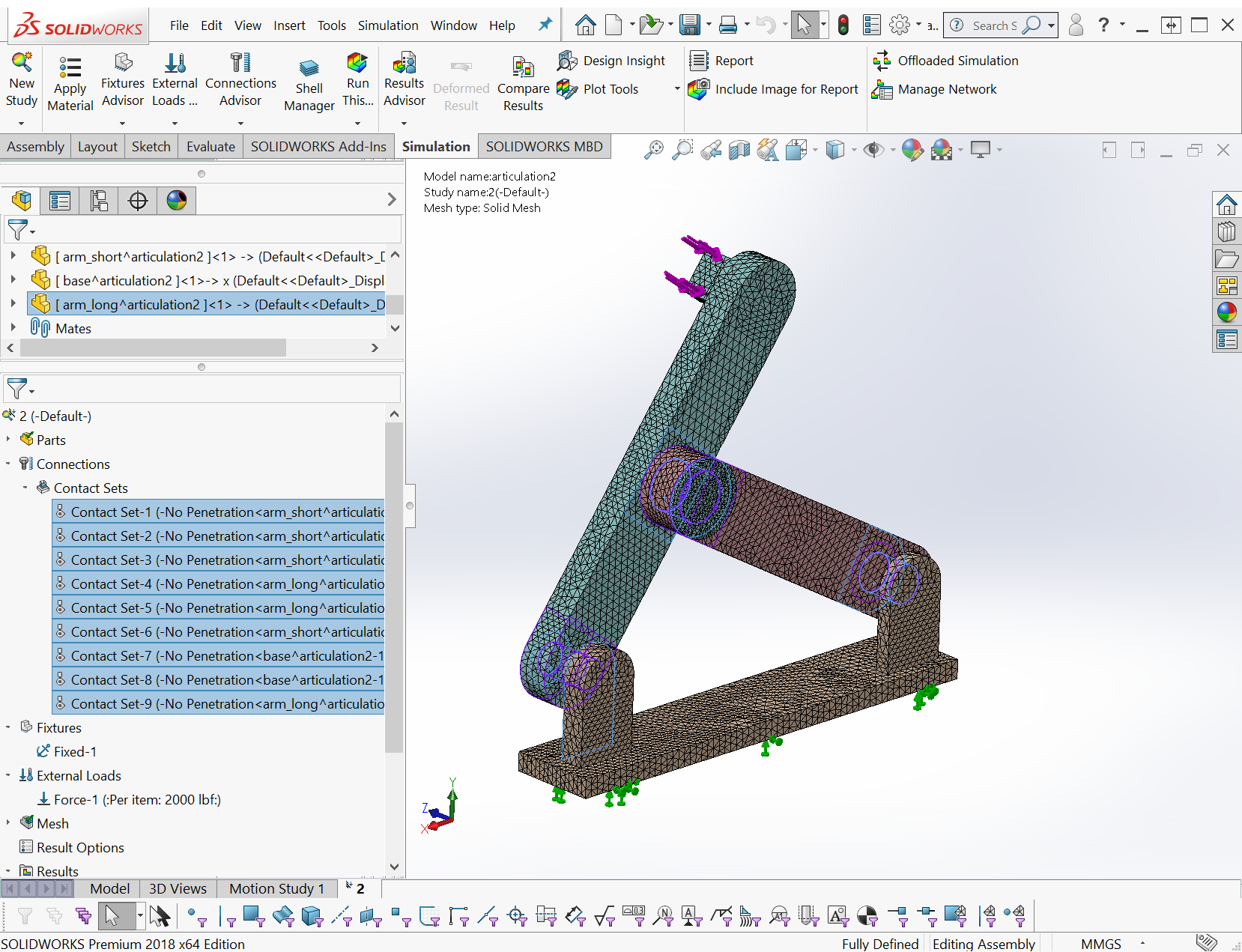
Mesh generation time for this study is minor. During the run it needs about 3.3 GB of memory.

The last study was run only on the newest box. It’s the real memory hog, taking over 30 GB of RAM to run through its 750,000+ elements. The direct sparse solvers are not compiled for much larger problems. To make this model an existing study was used with the element count jacked up much higher than necessary.
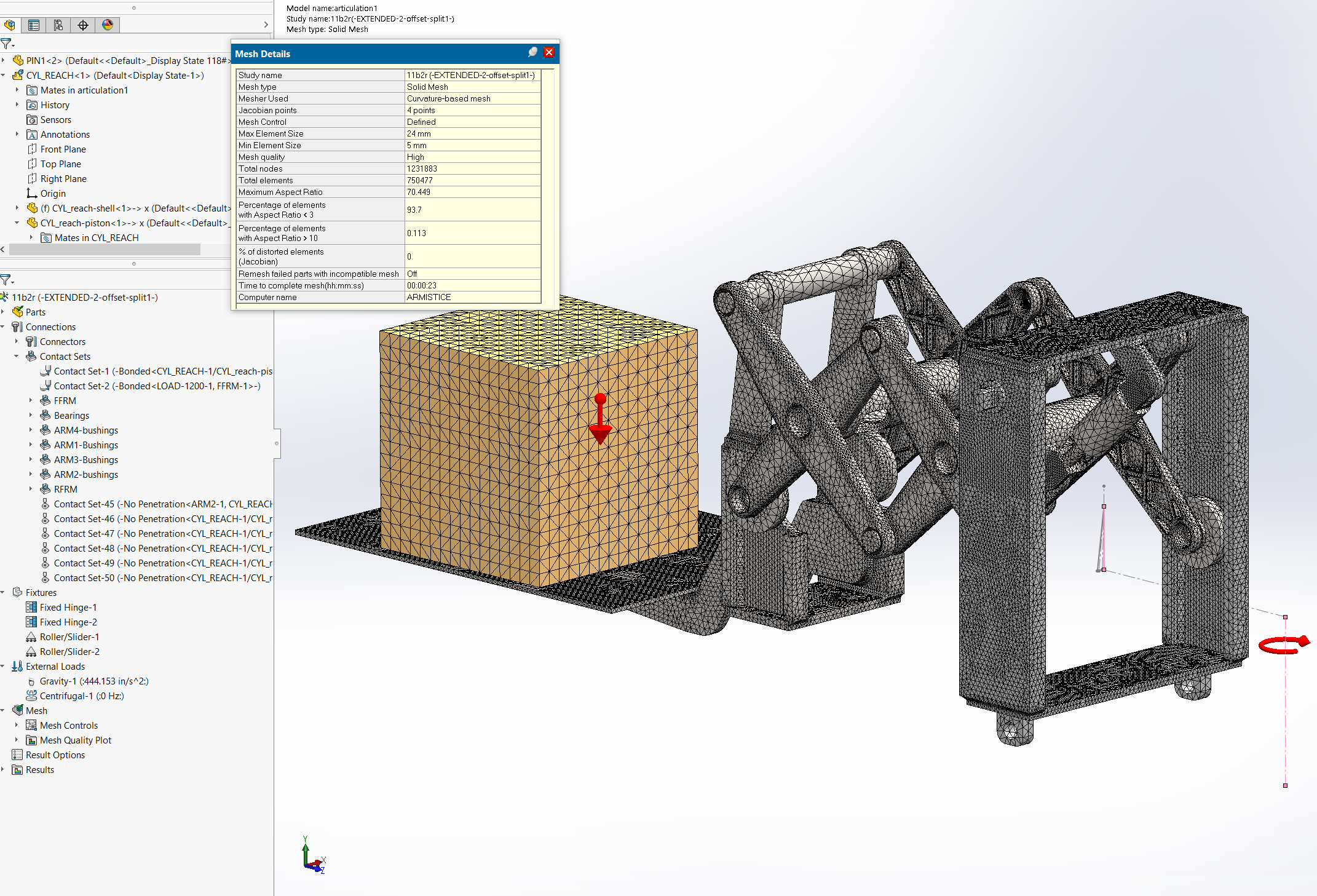
Let me reiterate – I KNOW THE MESH IS OVERLY FINE. The model gives usable results at half the mesh size. [Incidentally, if you think this is a large problem – note that similar pantograph mechanisms we’ve studied fit inside telescoping lifts, and we are routinely simulating them all together in full free contact.]

THE BENCHMARKS

I’m most familiar with the benchmark suite from Passmark. Their Performance Test 9.0 is used to generate a stack of comparable data.

THE SUBJECTS

A selection of Stone Lake’s own system were used, plus some borrowed time on two partner’s workstations.
– custom, 2012: i7-3770k, 4 core at 3.5 GHz, 667 MHz DDR3 RAM
– Dell T3600: Xeon E5-1650, 6 core at 3.2 GHz, 667 MHz DDR3 RAM
– Lenovo Y700 laptop: i7-6700HQ, 4 core at 2.6 GHz, 1067 MHz DDR4 RAM
– BOXX Apex2: i7-6700K (overclocked), 4 core at 4.4 GHz, 1067 MHz DDR4 RAM

Our new system was set up with a shiny new Intel i7-9800X processor, with quad-channel memory. It was set up bone stock, then given a mild overclock treatment.
– custom, 2018: i7-9800X, 8 core at 3.8 GHz, 1067 MHz DDR4 RAM
– custom, 2018: i7-9800X (overclocked), 8 core at 4.2 GHz, 1333 MHz DDR4 RAM

Other components in the systems are decent parts contemporary to the builds. The new box has two PCIe SSDs in a RAID 0 array, which is really screaming fast, but not much to do with the purpose today.

THE RESULTS

System specs, raw benchmark results, and Solidworks run times appear in the table below (click to expand).
Also shown are charts of the times against selected benchmark values.
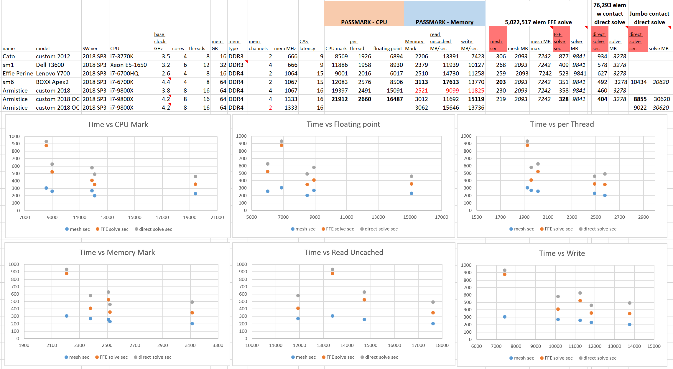
Obvious trends do not jump out from the charts. No one of the selected benchmarks is especially well correlated to Solidworks performance. In general it can certainly be said that newer hardware is better, but the expected leap in performance from quad channel memory just isn’t there even for the larger problem.

[A few good studies have been done of interest to us – Look at the great cores-vs-frequency study from Puget Systems. That article drove our choice of an 8-core system with relatively high clock.]

Since this isn’t a clean controlled study, where parameters are varied one at a time, we shouldn’t expect nice monotonic graphs every time, but the jumps here are curious. The first observation is that the memory performance of the newest system is pretty poor, in most benchmarks. The full set of memory tests appears below.

One certain thing is that the BOXX system’s memory performs fantastically well. I didn’t get a chance to dig into the BIOS, only getting what specs CPU-Z would report. I suspect some effort went into the memory timings at BOXX. As for my new build, it got whatever Crucial had preloaded in an XMP profile.

The higher core count chips excel in “threaded” memory access. This test involves the CPU cores directly in some way (I’m at the limit of my expertise here), so the result fits that one nugget of knowledge. I can’t say how much any of the memory benchmarks really lead to better Solidworks simulation performance.

It may be that memory speed was the bottleneck on the 667 MHz DDR3 systems I was using a while back. It looks like RAM can keep up plenty well these days. But for one last check I set up the “jumbo” study and moved DIMMs in the new system to dumb it down from quad-channel to dual-channel memory.

Dropping to dual channel the run time of our 31 GB jumbo run came in a whole 1.9% slower.

I can say that the CPU is still king. Full processor benchmarks follow.

The ultimate goal is to get good run times on big problems. For a final comparison the “jumbo” run was done on the two year old BOXX system. The new system, with comparable overclocking, comes in over 15% faster. I’m pretty happy.

Among modern core architecture (i.e. Skylake) chips, raw clock speed gets us the fastest meshes. A combination of clock and core count brings analysis results sooner. And since I think most users sit and wait for meshes to be made, as opposed to doing other things during the analysis, in Timoshenko’s name buy the fast chip!
Solidworks Simulation Chosen

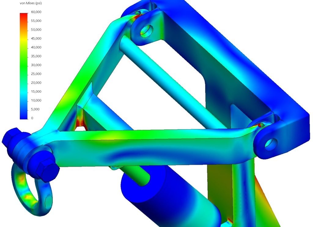
Solidworks Simulation has been selected as the primary tool for modeling and analysis at Stone Lake Analytics.

With a long history of both strategic acquisition and internal developments, Solidworks Simulations presents Stone Lake with an unprecedented depth of tool sets under a single interface. Shawn Mahaney, lead analyst for Stone Lake, has extensive experience working with Solidworks employees and VARs to push the limits of the package and see improvements be implemented.