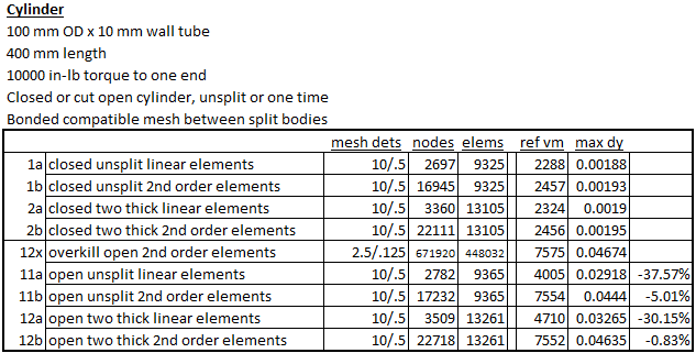
In the previous piece we looked at beam bending with solid and hollow sections, with different numbers of elements across the body or the wall thickness. Here we switch from bending to torsion. In torsion open shapes behave very different from closed sections.
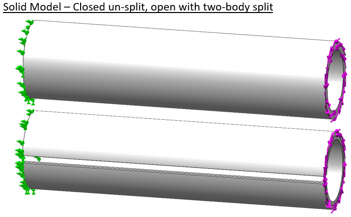
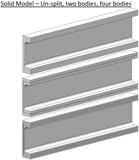
By closed section we mean something like the cylinder below. The section is made “open” by cutting a lengthwise slot through the entire length [the classic example for this is to take a whole toilet paper tube then cutting it once and seeing the difference in twisting stiffness].
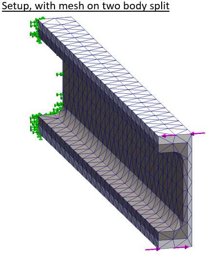
The cylinder is fixed on the left end. A pure torque is applied to the right end face. The second shape shows the slot cut and a split which cuts the shape into two bodies.
Again we mesh the body first with linear elements, then second order elements. The body is split to force multiple elements through the thickness at the same mesh settings. Since a closed cylinder is very efficient in torsion displacements are very small and we won’t plot displacement here.
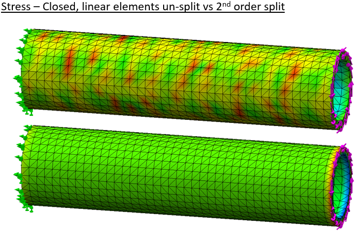
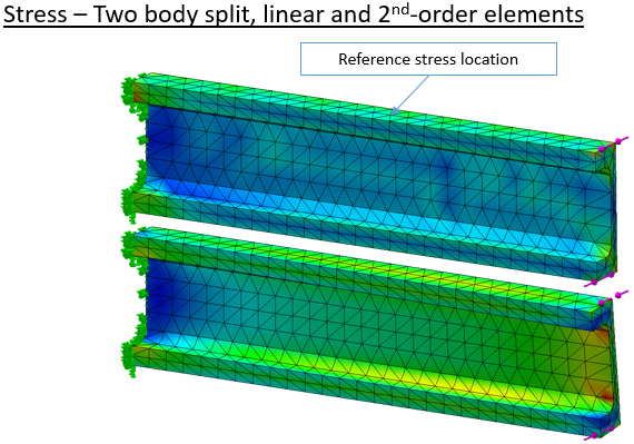
Results on the cut cylinder follow. Even with coarse linear elements the result looks realistic.
But when we use high quality mesh the body is much more flexible. Stress predictions also change significantly. The extremely fine mesh result is our reference.
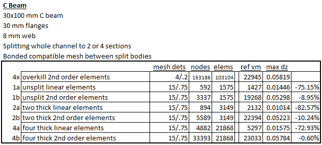
Tabulation of results shows again that the use of second-order elements goes a long way toward delivering ideal results.
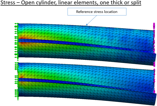
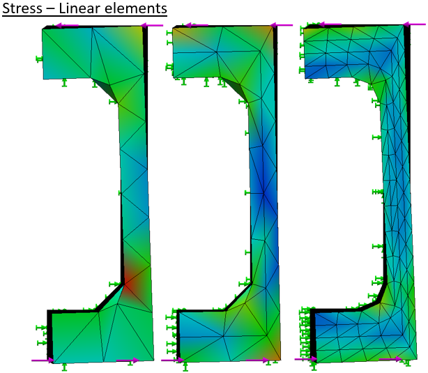
The engineer knows that asymmetric open sections are very poor in torsion, but sometimes that loading has to be borne. A simple C-channel is modeled and split into two or four bodies.
The setup has the left end fully constrained again. The right end has a moment applied by opposing forces along the top and bottom edges.
Stress results follow a now familiar pattern. With a coarse linear mesh the stress pattern is ‘lumpy’ and the deflection is very low.
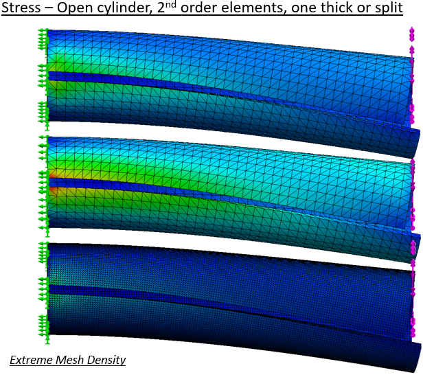
Viewed end-on the relative deflection is readily compared.
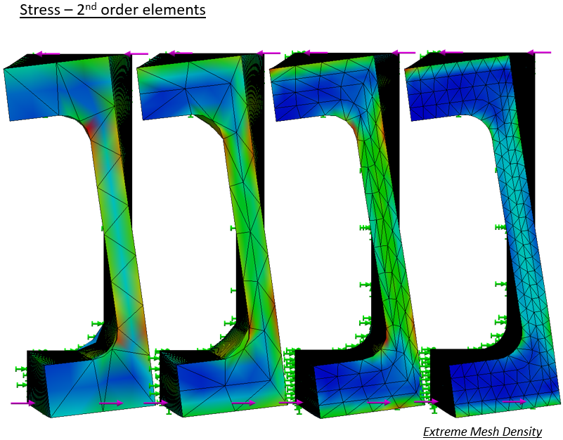
Twist of the high quality meshes is much greater at any density.
The tabulation shows the advantage of the “high-quality” mesh. In this case the mesh density needs more than two elements across the thickness to bring good results.
In conclusion we find that relatively coarse solid meshes with second-order elements usually provide good results in Solidworks Simulation. Relative importance of mesh density varies with local loading conditions. It is advisable to run mesh sensitivity studies, at least on any new class of problem. Our usual practice is to get what we think is a good result, then near then end of the project bump up the mesh density on one study to the maximum practical mesh size. After a long (maybe overnight) run, the results are compared to check that there is not a large divergence.
The claim comes up often when a FEA result is presented, “You need to have multiple elements across that wall!” Well, do you? It may be important to good simulation results. We’ll look here at when it matters and how modern tools can put us at ease.
The “when it matters” is a questions of both application and point in history. Some readers will remember the ‘dark ages’ of manually generating finite element meshes in Hypermesh on a 16 megabyte workstation, setting up command line batch runs that ran overnight and took all day to visualize. In those days computer memory and compute cycles were precious. Nodes and elements, usually linear, had to be placed efficiently or human and machine resources were overtaxed or tied up for overly long. Today computer resources are vastly cheaper while human time is ever more precious.
The “when it matters” of application depends on the geometry and loading. The purpose of a dense mesh is to capture important gradients in a solution. In structural problems we’re looking primarily at stress gradients and total displacements. In “boring” areas of nearly constant stress, coarse meshes are adequate. Good displacement results may require finer meshes even over smooth stress fields.
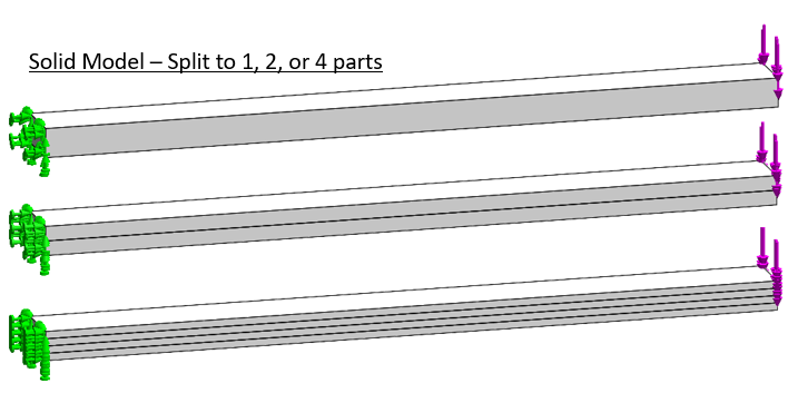
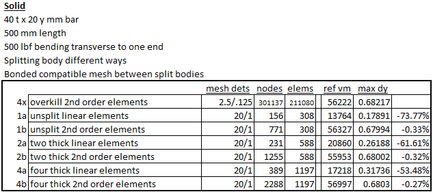
Here we will look at bending problems, starting with a simple solid bar. It is fixed on the left and loaded vertically on the right, a textbook cantilever.
This bar is split two or four times to force mesh refinement across the bending thickness. For reference an extremely fine mesh is also put on the body.
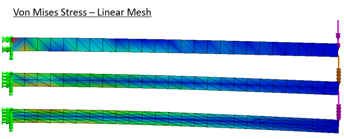
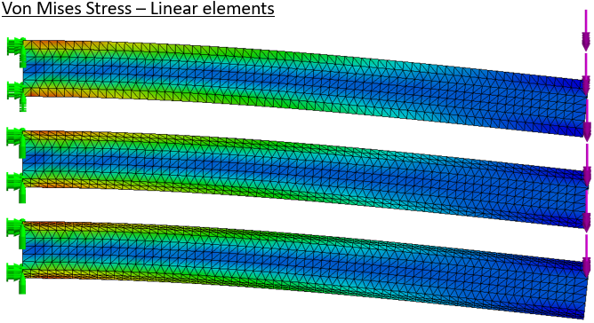
Deformed stress results are shown for meshes with linear elements. Total deflection clearly increases with mesh density, as the stress field becomes smooth.
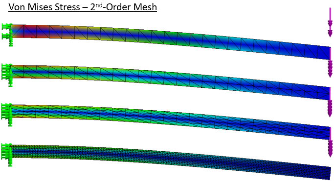
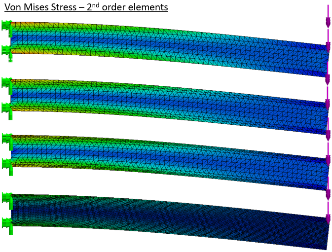
The same setups are run with Solidworks’ default “high quality” elements. Even with no refinement deflection is near as expected and the stress pattern is reasonable [stress color scales are all auto-scaled].
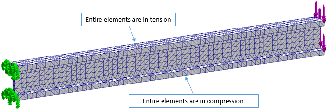
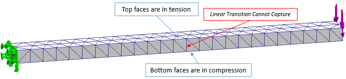
We can quickly discuss the issues here. With one element across the thickness, each tetrahedral element has one three-node face in tension or compression, and the opposite single-node vertex loaded the opposite direction.
Adjacent elements are loaded in opposite orientations. While the solver author has options in difference calculations (node centered vs. volume centered, etc), linear elements simply cannot resolve the stress gradients here. And if the base of one element is swelling next to the peak of another that is shrinking, that is another conundrum for the solver. It should be clear why tetrahedral elements especially are known for being “too stiff”. Rectangular brick elements would be better, but still cannot truly bend in one layer across the thickness of a beam.
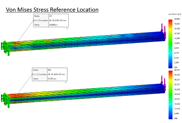
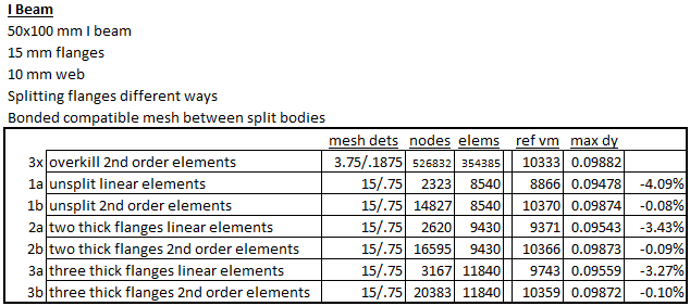
The results are summarized below. “ref vm” is the probed stress; “max dy” is deflection at the cantilever tip. The last stress plots show the typical stress probe location, and illustrate ‘lumpiness’ in the stress result with linear versus second-order elements.
Taking the extremely fine result as reference, the coarse linear mesh badly under predicts stress and deflection. Switching to second-order elements immediately improves the result. Doubling and quadrupling the mesh size barely affects the stress results and just nudges the total deflection. But if we stick with the linear elements progress toward a smooth and flexible solution is painfully slow.
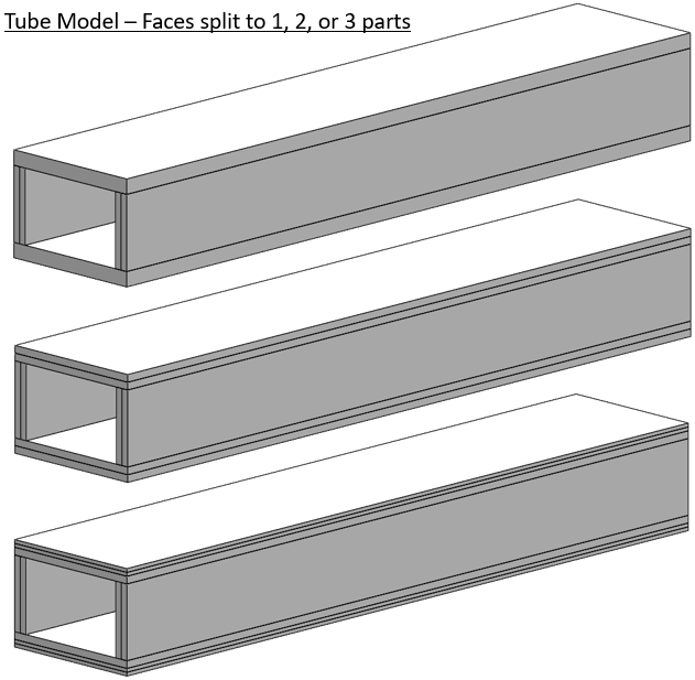
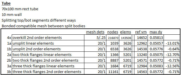
If bending is the primary load, an engineer will consider a shape like an I-beam. Here we have a simple beam with the flanges solid or split. We will repeat the meshing exercise, linear and second-order elements generated at different densities across the flanges.
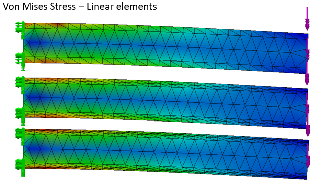
Right away we should realize a difference from the coarse mesh solid bar. Even with the coarsest mesh, the elements loaded in tension are separate from those loaded in compression.
Now the linear element meshes all perform in a realistic way.
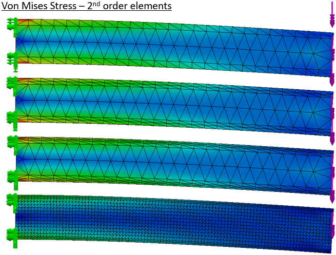
Response of the higher quality meshes can be differentiated in the numbers.
In compound or unknown loading, a closed section is the best choice. For comparison we will stick with a bending load and split the top and bottom faces.
Again the stretched and compressed faces are separated so linear elements give reasonable looking results.
With high quality elements the body is a little more flexible.
The stress results are pretty good even for the coarse draft mesh. The high quality mesh gives good displacement results even from the coarsest version.
What does this mean for the modern user? A mainstream workstation can solve multi-million element structural problems in main memory, and we often use direct solvers in Solidworks to breeze through 800,000 element setups in minutes. User time is much more valuable than computer time. We generally encourage people to stick with solid meshes and let the element count run up.
The challenge remains when long or thin portions of components are included. On high aspect ratio parts the element count can get extreme and Solidworks still does not give us tools to handle these sections efficiently. But we demonstrated here that coarse solid meshes on these “boring” connector sections can give usable results. Solidworks developers did us a huge favor by settling on the second order tetrahedral element, maximizing flexibility while retaining ease of fast automatic meshing. The user should focus mesh refinement on areas of detail and structural interest, like weld joints and contact interfaces.