Most FEA tools have a toolbox of handy features one can use to simulate mechanical elements. When not all the hardware in an assembly is modeled, or modeled badly, or modeled such that it makes interferences that must be resolved, these tools are as handy as a big hammer when the manual says “slip fit”.
We use a great many of the “pin” connector in Solidworks Simulation. Where holes (and/or shafts) are meant to be aligned or a body is supposed to have free rotation* it’s just a couple clicks to get the relationship established in Sim. Forces are transmitted cleanly and system response can be predicted well. But there is a catch – nodes on the hole or shaft walls are locked into relative position on the original theoretical cylinder. This has implications, locally at least.
[* in Solidworks 2018 the pin connector tool was improved to allow selection of more than two cylindrical surfaces, but free-rotation of the bodies was broken; a fix is promised for 2020.]
The following story is illustrated on a bespoke model, but inspired by a real story from a client who has some broken parts.
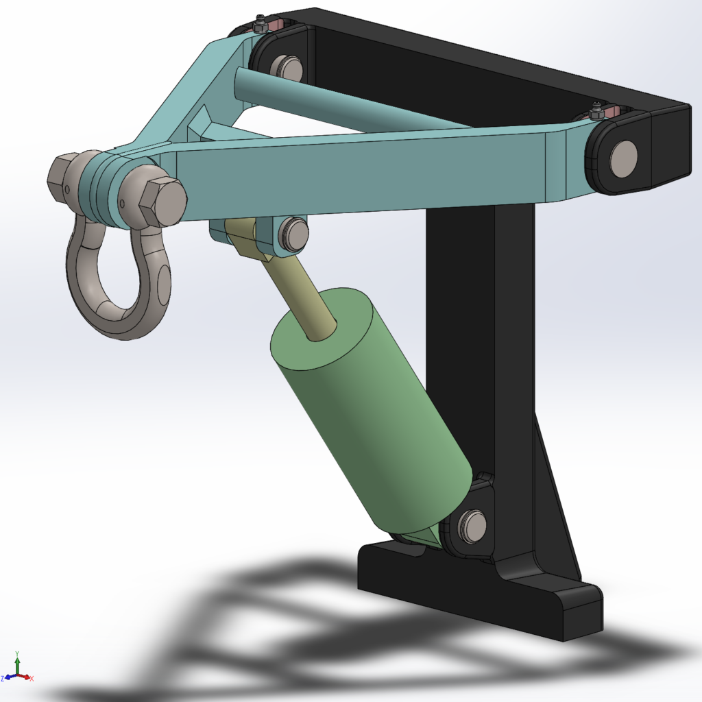
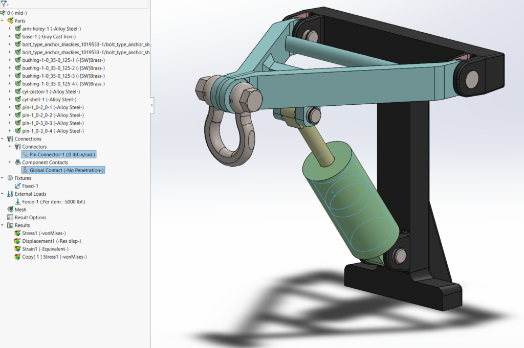
A small lift is modeled. A hydraulic cylinder raises and lowers an A-frame which has a shackle installed on the pointed end. The cylinder shell and the wide ends of the A-frame mount to a solid casting by pins through double-clevis joints. The assembly is about 18 inches tall with a 14 inch reach.
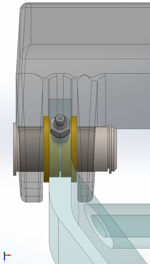
Most of the pin connections are plain bearings, and fairly loose. But it was decided that the rear joints of the A-frame should be tight, have brass bushings, and be greaseable. So the bore through the A-frame arms is larger, and there is a cross-drilled hole for a threaded grease fitting.
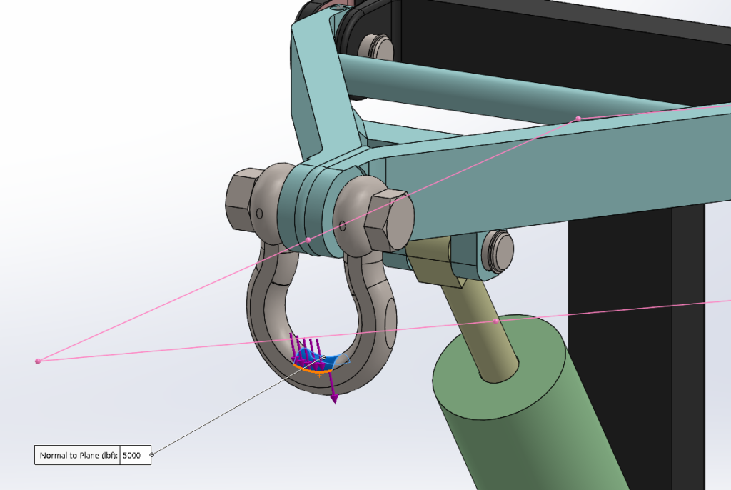
The customer wants to lift a two ton load, which is known to swing some. For our studies a 5000 lbf force is used, angled a bit to the right.
All the hardware came in the model, accurate (yay), not-overly-detailed (bonus), centered (wow), and close-fitting (excellent for contact analysis). But the fastest way to set it up is to exclude all the hardware and use the trusty pin connector.
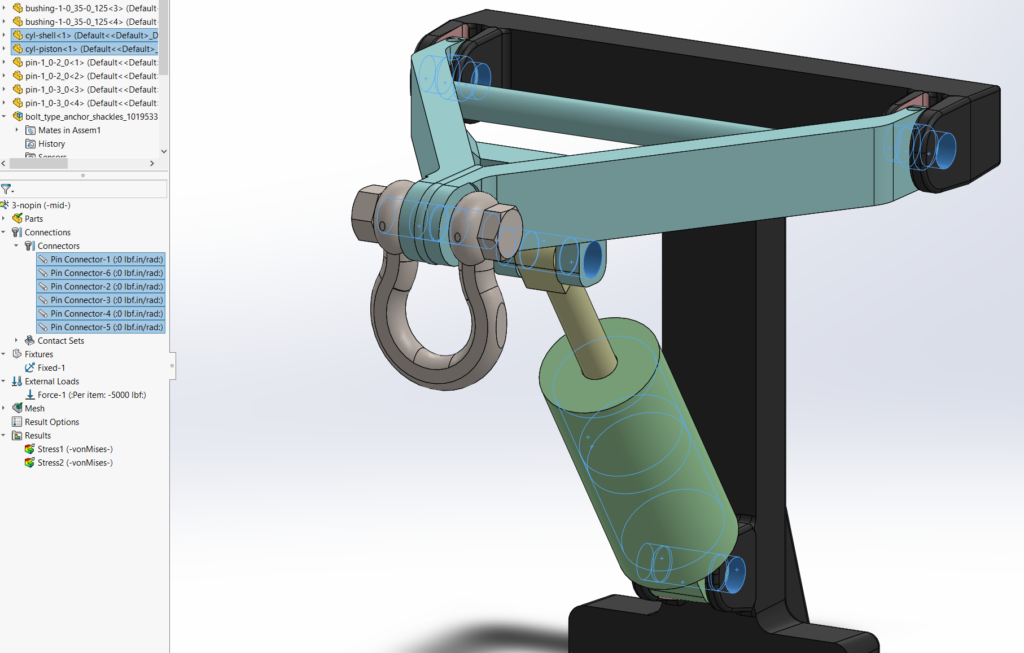
The modeled pins and pin-bushing sets are replaced by single pin connectors. Only the shackle remains, but it also is connected to the A-frame by a pin connector. (Another pin connector holds relative position of the cylinder halves.)
Since everything is connected by rigid “pins”, the FEA solution is practically a static solve of a single solid body. It runs in 24 seconds.
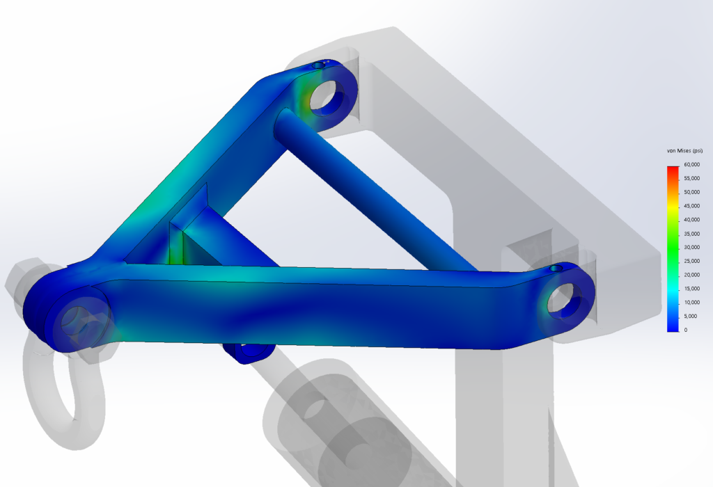
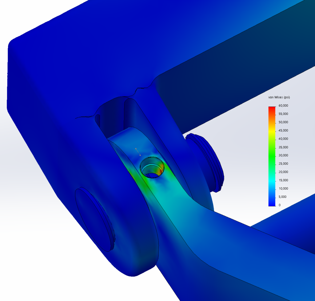
Stresses in the wrought steel frame look pretty good. But what about that grease fitting hole? It left some pretty thin walls. Some mesh refinement was put around here and a closer look taken.
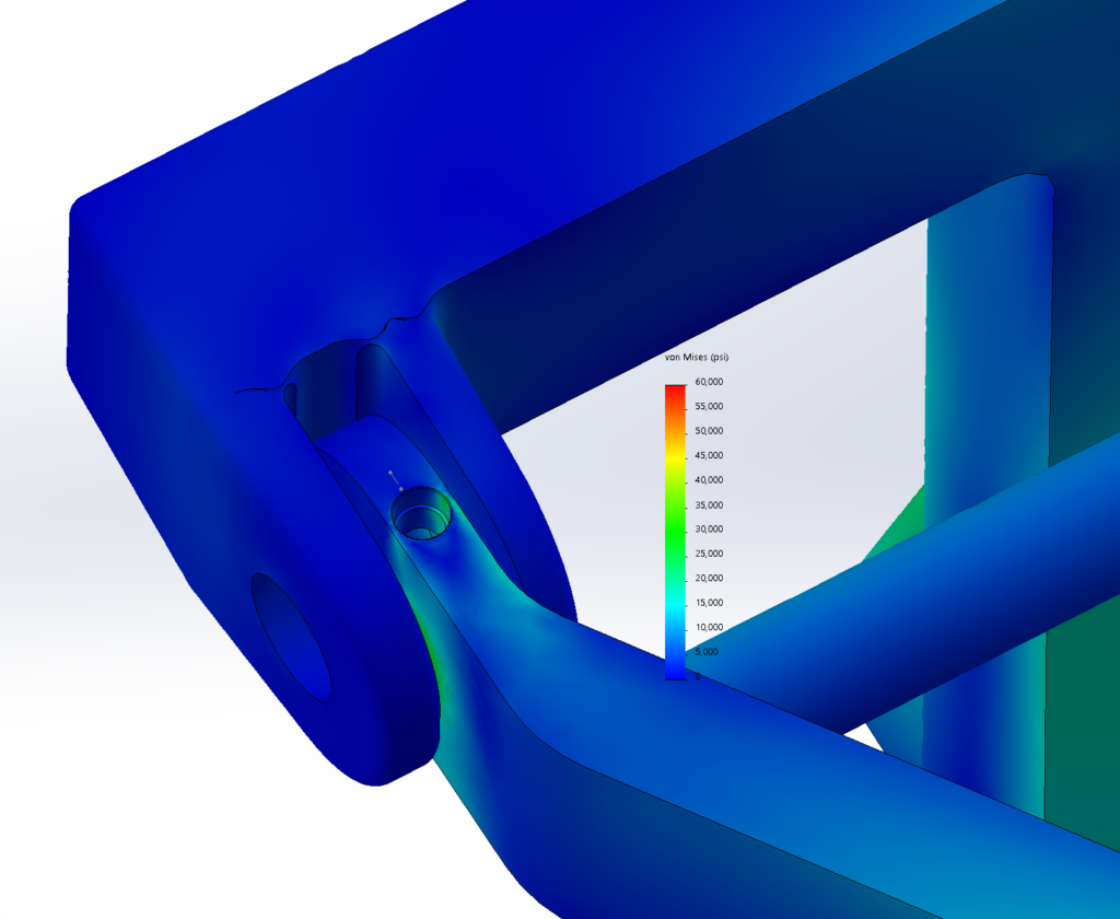
Ok, the thin walls are working hard, but it still looks good enough. Since it runs fast, we can set up runs with the cylinder at all different strokes to see what happens, generate all kinds of force data, and keep the customer happy. …Until something breaks and they want to know why.
Setting up this problem the hard way, i.e. the right way, means ditching most of the pin connectors and using the supplied hardware (or custom modeling simple hardware to do the job in Sim).
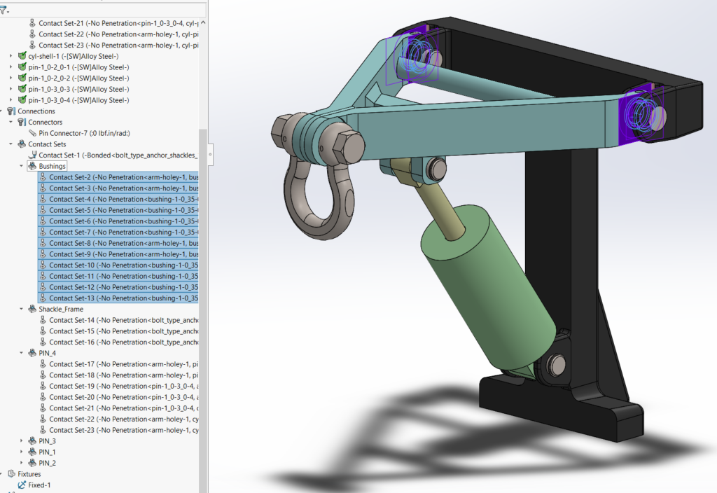
Over 40 high-accuracy no-penetration contact pairs are manually defined. At every joint each part is in contact on a cylinder and two lateral faces. Only the cylinder’s pin connector remains.
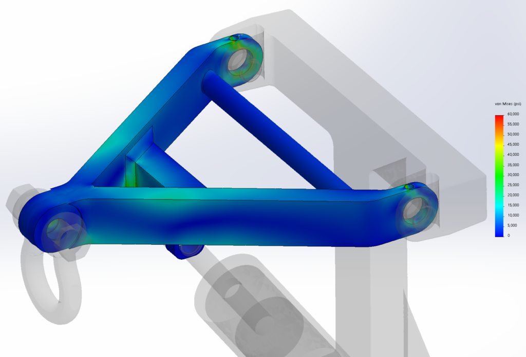
The stress pattern is very different in the mounting ears. Elevated stress is seen all the way around the joint, whereas on the first run it was only on the load side.

Now the full stress concentration from the drilled hole is captured. Further study can show how the stress might be sensitive to dimensional variance, like the hole being off-center.
At what cost did we get the better answer? It took about 20 minutes to set up all those contacts, and 25 minutes to run the study, versus a few minutes and 24 seconds to run the all-pin study. It beats getting a phone call from an angry end user who’s standing over a hole in the ground, made by some expensive equipment that just got dropped.
Incidentally, while all the setup work was going on, another easy-setup study was running.
Since it looked like the geometry was clean and complete, on starting Sim the simplest possible study was started. A single input of global no-penetration contact is used in place of pretty much everything else. This is almost always worth a try. It can take a lot of computer memory, and sometimes a long run time, but this study can run while all the other human work is being done on the ‘real’ setup.
In this case the quick-and-coarse study found the hot spot. With a couple mesh refinements it should match the answer in the full-manual-contact study. And it ran in under 13 minutes, quick enough that it could have guided all the later work.
Features like pin connectors are great, but the analyst has to understand what effect they have on the local situation.